I Seeeeee Youuuuu
Fri 25 March 2011
So, first steps. I picked up a few PIR Motion sensors. These are a specific kind, there are a few other kinds, but they should have datasheets. You might recognise the bulbous white shape of them from those motion-sensing light switches. They're about a fiver each and fun to play with.
The comments section on Sparkfun had a very good tutorial on basic use, but also explains the basic principles of its operation. It has 3 pins -- DC, Ground and Alarm.
Science Bit
The alarm pin is what's called an Open Collector, which means it's either connected to ground, or to 'nothing'. To better understand this, let's assume you don't know what a transistor is (I know I sure didn't a few weeks ago).
Speaking simplistically, a transistor is a component where you can vary one voltage based on a much smaller voltage. In this way you can amplify a voltage pretty easily.
Here's a diagram!

Usually transistors are tiny and embedded or are tiny and on a breadboard, but let's assume for a moment that it's a box with 3 wires coming out of it. They're called collector, emitter and base. Emitter is always connected to ground, and provides the reference voltage, or definition of 'zero'. Base is a small voltage in relation to ground, and the voltage applied to the base controls how much voltage is allowed flow between the emitter and the collector. The difference between the voltage on the base, and the voltage allowed through the collector is called the 'gain'.
However! The voltage on the collector doesn't come from nowhere. It has to be supplied, and the voltage 'allowed' to flow is defined by the voltage on the base. So, if you apply 3.3v to the base, and 9v to the collector (the voltage marked 'V~cc~' on the diagram there), you get a certain voltage that's actually 'allowed' through the transistor, and can be used in other applications by connecting them before the resistor (At 'V~out~' on the diagram).
The zig-zaggy thing there on the diagram is a resistor. We put it across the larger V~cc~ voltage to lower it a bit, since transistors are usually only rated to take a certain voltage. The function of V~cc~ and the resistor is to 'pull up' the voltage across the emitter and collector. This is why the resistor there is often called a 'pull-up resistor'.
Transistors are handy for switches when you want to control a large voltage using a small voltage. They're also useful if you want to take a tiny voltage you get from a signal somewhere and amplify it.
Anyway, why this is relevant is that an 'Open Collector' is the collector from a transistor that's available as a signal. However, instead of usual 'binary' signals that might produce a 'True' voltage or a 'False' lack of voltage, it's either connected to ground, or not. Whether or not it is connected to ground depends on the base voltage. My guess is that the PIR sensor circuitry provides the 'base' voltage and lets us use any V~cc~ voltage we want, in order to 'pull up' the output.
So, if you go look at the circuit diagram and build instructions in the tutorial mentioned above, it works just so. The one modification I made here is that as well as pulling up the voltage, instead of connecting back to the LED on the Arduino board, I connected up to a big old Piezo Buzzer I got in Maplin.
The finished build looked like this:
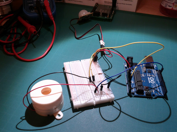
So, the end result is that when you wave your hand in front of the PIR, the buzzer makes an annoying noise. Success!
Next up would be making things a bit smaller -- There are smaller, cheaper Arduino boards you can get, and I'll do a build soon that's a little easier to get into a project box and lug around with you.
Category: Tech Tagged: imported arduino electronics